FORUMula1.com - F1 Forum

Discuss the sport you love with other motorsport fans

Dedicated to technical discussion...
#280467
Mercedes invents front wing F-duct for 2012 - report

Mercedes plant F-Schacht im Frontflügel

With an aggressive development program, Mercedes in the season 2012 finally wants to start through. A project is there the F shaft in the front wing. We ventilated the secret around the brilliant technology trick.

One cannot reproach Mercedes that the engineers would have no ideas. The Mercedes MGPW02 is an unusual car. With courageous ideas in many branches: the wheel state short, the draft with the folded Kühlern and the revolutionary load work that networks the four suspensions hydraulically together.

Yet the technologies tricks did not bring however that until now, what promised the theory. Nevertheless team boss wants to want hold horse Brawn at the philosophy of the aggressive development. "To be sure something fewer extremely".

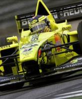
Mercedes tests reports front wing trick in Suzuka such as car motor and sport in its current edition (notebook 23/2011, as of 20 October in the trade), becomes one of these projects a F shaft in the front wing. In order to go on number certainly, one tried the system very secretly already once. In the first Friday training of Suzuka. The engineers used the training in order to gather data. In the wind canal is the F shafts problematic nature only heavily representable.

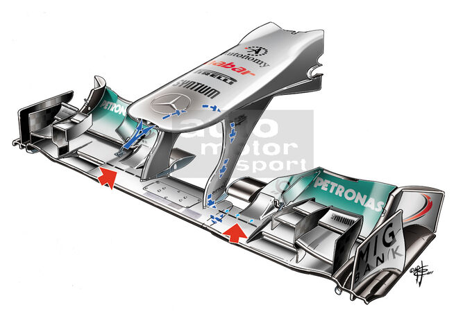
Only he who viewed there very exactly, Mercedes came would slink on that. Normally the oval hole in the nose tip of the MGPW02 is sealed. In Suzuka, it was open. One saw a hole divided in the middle. Through this, air is initiated into the front wing. Example for the system is the F shaft in the stern wing that came in the before season in fashion.

Better Anströmung of the subsoil and more Top Speed the air is led then over a direction system through the front wing stilts into the right and left part of the head leaf. If the dynamic pressure exceeds a certain measure, the air blows at the underside of the wing over altogether four slits off. The driver must not the system therefore like in the F shaft in the preceding year manually aktvieren.

Through the trick, the current is calmed under the wing direction subsoil. And it serves the Top Speed. Around how much, about that the experts are themselves disagreeing. McLaren boss Martin Whitmarsh appreciates between five and eight km/h. It reprimands however on that that this technology would be to got heavily into the handle. Mercedes could have pulled therefore the jackpot with its early development start. "Who now therewith begins, is already late at it".

Only passive F shaft at the front wing permitted actually is forbidden the F shaft. Actively anyway. The driver may interfere no longer. On a passive F shaft in the stern wing, with which the dynamic pressure determines when the current should dismantle, renounce the teams voluntarily. For that the FIA gave them the DRS wing. It brings clearly more Top Speed if one may flat place the stern wing Flap at the push of a button.

For the front wing, there is no Regularien. There a passive F shaft is legal. Whitmarsh believes that now also other teams with this technology will busy themselves. The technical Reglement is so restrictive that one must use each small loophole. Mercedes goes not only personnel an aggressive strategy. One wants to set also technically trend. 2012 are podium places duty.

In our picture gallery, we show you very exactly how the trick functions.


Image
#280470
Don't many cars have that same system already? I remember seeing that opening in the front of the nose on a couple of cars... is this Mercedes playing catch up or is this Mercedes throwing a curve ball for the rest of the teams, I can't see Mercedes releasing their designs, giving the other teams a chance to copy the design... that really isn't very F1 like!
#280479
The opening on the nose has been there for years but apparently this system is new and was tested at the Japanese GP for the 1st time.

I actually read this article earlier today, it just doesn't add up; giving away all their secrets before the start of next season is just crazy... I still think it's a red herring!
#280499
The opening on the nose has been there for years but apparently this system is new and was tested at the Japanese GP for the 1st time.

I actually read this article earlier today, it just doesn't add up; giving away all their secrets before the start of next season is just crazy... I still think it's a red herring!


Yes, that's what I'm thinking! Surely not wise to proudly reveal a great design secret to your rivals (some of which are better than you already) before testing has even started?!?! :confused:
#280503
The small ducts at the front of the nosecones are there to cool the electronic boxes and/or electric power steering assemblies mounted at the front of the tub.

I'm pretty sure they aren't there to cool the drivers. They are in 3 layer nomex suits, so any air getting in there won't do anything to help......also aerodynamically, you want to minimise any airflow through the car if you can avoid it, as it results in a little extra drag.

Cheers,

Pat
#280505
The small ducts at the front of the nosecones are there to cool the electronic boxes and/or electric power steering assemblies mounted at the front of the tub.

I'm pretty sure they aren't there to cool the drivers. They are in 3 layer nomex suits, so any air getting in there won't do anything to help......also aerodynamically, you want to minimise any airflow through the car if you can avoid it, as it results in a little extra drag.

Cheers,

Pat


Are you sure? I've read elsewhere it's driver cooling, suit or no suit. Bit of airflow would always be cooler than none.
#280510
I was cracking up reading the english translation LOOOOOOOL

"Nevertheless team boss wants to want hold horse Brawn at the philosophy of the aggressive development. "To be sure something fewer extremely".
HORSE BRAWN!!
#280511
Mercedes’ new idea is to redirect more undisturbed air through the floor of the car.


My limited understanding of aerodynamics tells me this would create higher pressure under the car, and thus less downforce. right?

if anything, they should be trying to take air OUT from under the car. put holes at the bottom of the front wing, and through a duct over the top of the car.

but then I'm not a highly-paid F1 aerodynamicist.
#280514
I was cracking up reading the english translation LOOOOOOOL

"Nevertheless team boss wants to want hold horse Brawn at the philosophy of the aggressive development. "To be sure something fewer extremely".
HORSE BRAWN!!


I put it through an on-line translator so don't complain unless you can speak German and provide a better translation. :wink:

The small ducts at the front of the nosecones are there to cool the electronic boxes and/or electric power steering assemblies mounted at the front of the tub.

I'm pretty sure they aren't there to cool the drivers. They are in 3 layer nomex suits, so any air getting in there won't do anything to help......also aerodynamically, you want to minimise any airflow through the car if you can avoid it, as it results in a little extra drag.

Cheers,

Pat


Are you sure? I've read elsewhere it's driver cooling, suit or no suit. Bit of airflow would always be cooler than none.


Could be both.
#280520
I'm pretty sure that they are not for driver cooling. The path through the nosecone and the cockpit bulkhead is a tortuous one, going past the electronic boxes, brake fluid reservoirs, steering rack, and the drivers pedals and feet. Believe me, the driver wouldn't even feel any difference in temperature. We humans dissipate most our heat through our heads, hence why the helmets have the air vents......

In any case, weren't the regs especially rewritten to ban f ducts, or similar driver operated aerodynamic devices? In any case, you'd clearly see ducts at the monocoque bulkhead, and in the nosecone...

Personally, I think it's just some scuttlebutt.....
#280529
I just remember Brundle talking about the hole in the nose, when Ferrari brought out the hole through the nose cone in 2008 he was saying the driver vent is now gone and the only cooling the Ferrari driver will get is from the open end of the cockpit.
#280530
[youtube]r2WnLNbkpOw[/youtube]

Scarbs is tweeting this http://www.caranddriverthef1.com/formula1/articulos/2010/08/10/f-duct-automatico-y-espanol-un-proyecto-para-2011. Not sure why they used an onboard of the MP4-20 but I think its just an example, you can see the device work during the corners and straights etc.


Automatic F-Duct and Spanish: a project for 2011
Its inventor explains how to adapt to new regulations
The F-Duct is prohibited in its current form since 2011, but the Spanish engineer Zuriguel Diego Cano has developed an automatic system without the intervention of electronics by which cars could benefit from a lower downforce at peak times, as happens now.
By Diego Cano Zuriguel
0 Comments | 10 Aug 2010 - 12:19
Send to a friend Print


Automatic F-Duct DUCT F-AUTOMATIC PHOTO
A passive system administration through automatic F in a Formula 1 car, this concept is meant to relieve the pilot of F through manual control and operate all or part at all possible times when it is beneficial and safe. To get more chance of being accepted for incorporation by the current regulation, this system will be passive, so you can not use any external control-mail.

Nor is there reason to ban it in the next season, because as recently approved by the FIA: "Any other system (referring to future adjustable rear wing) movements requiring the pilot to alter the aerodynamic characteristics of the car will be banned since 2011" .

Video demonstration - F-Duct Machine


For its operation, we will use our own forces G generated in the car. These are the G forces that control the operation of the system, contain useful data for the state of the car in every part of the circuit. For example:

The rapid acceleration in straight or curved, indicating that the car or out of unemployment, slow or is coming off a slow curve after this one. In any case, it must turn off the tube F to get better traction.
Braking, which indicates that the car is prepared to draw a curve slower than your actual speed or need to slow down or stop. In any case, it would be necessary to disable the F-duct to enhance braking and get more grip to draw the impending curve.
Left or right curve indicates that a curve is more or less demanding, for which completely deactivate through F in the most demanding part of this curve and in the lighter.
Stable G-forces, indicates that the car is stopped or is in a long straight or straight lines cut one or more consecutive curves, so the primary speed grip, for which the duct F to activate these forces G no longer stable.
This system will be incorporated into the conduit containing the hole must be plugged now by pilots to operate the F-Duct (Fig. 1)


Figure 1 Section of pipe and orifice that taponaría to drive the F-Duct.


This part will place the main part of the system, defined as "actuator" (Fig. 2). This piece can be moved freely along the canal and turn around, and is basically a tube inside another. By submitting this actuator G forces supporting the car, moves forward under braking and acceleration backward while turning to left and right curves in curves right to left.


Figure 2 Actuator


Pala limit the movement of this piece and it returns to its initial position when the G forces are stabilized coupling a spring (Fig. 3) to one end of the actuator, which will set the tube through the other end and the actuator for focusing that covers the opening drive of the F-Duct in the absence of rapid acceleration or braking and releasing this hole when any of these conditions in proportion. For this system to rotate around the duct orifice and release curves, incorporate a bearing (Fig. 3) between the spring retaining and conduit.


Figure 3 springs and bearings


Like the need to limit the movement of the actuator acceleration and braking, it is also necessary to do so in the corners. This grip the bearing that holds the spring with rubber bands, springs or small buffers (Fig. 4) then we will post at the other end into the duct. Thus, the actuator will also return to its initial position after each rotation curve.


Figure 4 Attaching the bearing to limit its rotation


Finally incorporate the actuator properly balanced system (Fig. 5) to facilitate the movement of the G-forces by


Figure 5 Example of checks


The actuator may be modified according to the characteristics of each circuit by changing three simple dimensions (Fig. 6).


Figure 6 Adjustment of allowances


Furthermore, the characteristics of spring and counterweights or dampers gums may also suit the needs of each circuit. You can also enter another spring and bearing system (symmetric to the first) to the other end of the actuator to better control their movement and recovery during braking.


Passive management through automatic 3-way F

With the previous system opens the possibility of administering more than one canal F simultaneously. In this case, the F-Duct administer standard plus two additional F-Duct, one would have to be designed to facilitate left-hander as one for right-hander. These F-Duct additional downforce could take something which is most convenient in each case.


Video simulation of operation: F-Duct three-way


To avoid gaining weight and dimensions that would be the placement of 3 separate systems, use one of these systems divided into 3 parts inside the duct (Fig. 7) and making two more holes in it. Thus, each time one of the holes clogging control for the F-Duct without disrupting the other two.


Figure 7 details the duct triple


These additional holes are plugged only in their respective corners and where there is both quick acceleration or braking. The size of the holes and shape can be varied to suit the characteristics of each circuit.

See our F1 related articles too!